In this paper, the 3D geometric model of the connecting rod is established by using the 3D computer aided design software Pro/E and saved as a file in IGES format.
In the integrated environment of ANSYS Workbench, the IGES format file is imported into Workbench through the reader mode to establish the finite element model of the connecting rod. The modal distribution of the connecting rod and the vibration mode of each mode are obtained through calculation. Analyze the calculation results and point out the weak links of the connecting rod.
Establishment of 2-link finite element model When modeling the solid structure in three dimensions, the following methods are often used: (1) Direct modeling in ANSYS or ANSYS Workbench, suitable for models with simple structure.
(2) Establishing a 3D model in 3D CAD software, importing the model through the interface with the analysis software, suitable for more complex models, but the model is easy to make mistakes after importing, which brings difficulties to the division of the next grid, and repairs the model. It takes a lot of time and effort.
(3) Create a 3D model in 3D CAD software, use CAD interface to read into Workbench in plug-in or reader mode. This method can import 3D model correctly and directly, and directly divide the structure into AWE platform. And carry out the corresponding analysis.
In this paper, the third method is used to establish the three-dimensional geometric model of the connecting rod by Pro/E and save it as a file in IGES format. Imported into Workbench via reader mode. In the meshing of geometric models, the default options in Workbench are used to divide the connecting rod into 9275 units and 15253 nodes. The meshed finite element model is shown in the figure. The coordinate system takes the length of the connecting rod as the X-axis, the center line direction of the large round hole of the connecting rod is the Y-axis, and the Z-axis is determined by the right-hand rule.
The finite element solution and the result analysis of the 3 links are used for plane motion, and both ends are limited by the piston pin and the crank pin. To this end, a cylindrical coordinate system is defined on the axis of the hole at both ends, and the point on the hole end has a degree of freedom of rotation about the axis. The mode is determined by the inherent characteristics of the system and is independent of the external load, so no load boundary condition is required. The dynamic characteristics of the EQ1141G air compressor connecting rod are analyzed by using the three-dimensional finite element model established above, and the cutoff frequency is analyzed by default. The 20th order mode of the connecting rod is intercepted.
It can be seen from the calculation results that the modality of the connecting rod is relatively dense, and there is a 9th-order mode between 100 and 2000 Hz. In addition to 300 to 400 Hz, 500 to 600 Hz, 700 to 1000 Hz, 1300 to 1400 Hz, 1800 to 2500 Hz, and 2900 to 3400 Hz, there is a first-order mode for every 100 bands, and at 2000 to 4100 Hz. The modes between the two are mainly distributed in the frequency range of 3400 to 4100 Hz, and there are 7 modes, and the difference between adjacent two modes is not very large. The vehicle compressor is in variable working condition and variable speed condition. The connecting rod needs to bear the gas force transmitted by the piston, the inertial force of the reciprocating mass and the inertial force generated by the self-oscillating motion during the working process, and the oversized bearing is generated. Assembly stress and pre-tightening force of the bolt. The change in inertial force is related to the rotational speed of the compressor. The frequency is usually the harmonic of the fundamental frequency of the engine's drive source DD. The gas force can be regarded as a pulse excitation to a certain extent, and its frequency range is wide.
It can be seen that in the first 8 modes of the state below 1700 Hz, the vibration modes of the connecting rod are various, and the concentrated expression is bending vibration. The first order, the second order, and the third order are bending vibrations around the X-axis, the Z-axis, and the Y-axis, respectively, with a slight twist; the fourth order is the local vibration of the small end of the connecting rod; the fifth and sixth orders The modes are 1st and 2nd order bending vibrations around the Z axis and the Y axis; the 7th order is the bending and torsion composite vibration of the connecting rod; the 8th order is the 2nd and 3rd order bending vibration around the Z axis. Under all the overall vibration modes, the large and small round holes of the connecting rod are out of round. The loss of the hole will cause the big head and the crankshaft connecting rod journal, the small head and the piston pin to lose normal cooperation, resulting in a series of faults such as common holding tiles, burning tiles, and fatigue-reducing materials. The bending vibration of the connecting rod causes the piston to be skewed relative to the air sleeve and the journal relative to the bearing, causing additional stress, causing cracks and damage.
It can also be seen from the vibration pattern that when the bending vibration and the bending and torsion are combined, the structural shape of the connecting rod changes the most, and there is a significant node position.
The nodes of the first-order, second-order, and third-order bending modes are in the middle of the link, and the node positions of the fifth-order bending-torsional vibration modes are basically the same as those of the sixth-order bending mode, and the node positions are 2 , respectively, in the joint part of the connecting rod shaft and the connecting rod small head and the joint part of the connecting rod shaft and the big head; in the 7th order bending and torsion composite vibration, the node is in the middle of the shaft, stress concentration occurs; the 8th order bending vibration type There are two nodes, one in the middle of the link and near the small head. Therefore, when designing the connecting rod, it is necessary to consider not only the influence of the stress concentration of the joint between the shaft and the large and small heads, but also the influence of the middle part of the shaft and the dynamic characteristics of the connecting rod on its fatigue strength.
4 Conclusions (1) The analysis of the dynamic characteristics of the connecting rod is the supplement and development of the static design, and it is an important means to rationally design the connecting rod structure and improve its reliability.
(2) The modality of the connecting rod is dense, especially the first and second order modal frequencies are low, and it is excited by the air compressor during the working process, which is relatively easy to cause resonance response, causing some parts of the connecting rod to move. Excessive stress should be taken into account in design improvements.
(3) The stress concentration of the connecting rod is generally at the joint of the big and small heads, but the stress concentration in the middle of the shaft is also obvious. Therefore, the traditional design concept should be changed, and the middle part of the connecting rod should be fully considered in the design.
(4) Cracks are easy to occur due to bending vibration, so it should be fully considered during design to avoid excessive bending vibration and reduce fatigue damage to improve the service life of the connecting rod.
(5) It is effective to analyze the dynamic characteristics of the connecting rod by the finite element method.
Overview: Honing is to use the honing head honing workpiece and finishing on the surface of the grinding machine. It is mainly used in automobile, tractor, hydraulic parts,
bearing, aviation and other manufacturing industries to honing the workpiece
hole. Honing Machine has vertical and horizontal two kinds.
Our company main product Vertical Honing Machine(half automatic and CNC ) and Horizontal honing machine.
Classification and characteristics:
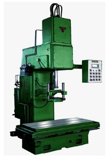
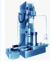
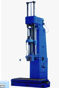
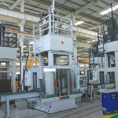
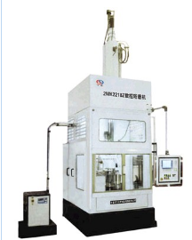
1.vertical honing machine spindle working travel shorter, suitable for honing cylinder body and casing hole, etc.With oil stone Mosaic honing head driven by the placement of the vertical spindle rotation, at the same time in hydraulic device driver operating vertical reciprocating feed movement.(see picture)
2.Horizontal honing machine work schedule long, suitable for deep hole honing, depth of up to 3000 mm.The placement of horizontal honing head not rotating, axial reciprocating motion, workpiece by the spindle drive rotation, for lathe bed in the middle of the workpiece at the center of the frame and the supporting honing rod guide frame.In the machining process, the honing head oil stone in swell-shrink institutions operating radial feed, the workpiece processing step by step to the required size.A new type of honing machine adopts hydraulic swell-shrink honing head.Most of honing machine is semi-automatic, often with automatic measuring device, can also be incorporated in the automatic production line of work.In addition to processing hole honing conversion, processing and other surface of the cylindrical honing machine, bearing raceway honing machine, flat honing machine and surface honing machine, etc.(see picture )
Operation requirements
1.Honing machine operation has a certain technology, need a understand technical person, this person should be trained about grinding safe operating methods.And make necessary preparation before operation can be carried out
2.Check the lubrication part of the honing machine, especially the gearbox, see if there were any lubricating oil.If there is no oil, to all the oil injection hole filling.
3.Check coolant cleaner.If insufficient cooling fluid, coolant will be listed.Coolant to regular cleaning, not allowed to use a squalid coolant.
Continuous work two months later, the need for an oil change.Under normal circumstances, in the first quarter in oil at a time.The hydraulic oil 20 # engine oil should be adopted in general.An oil change, need to use kerosene oil filter and oil tank cleaning.
4.After the machine is idle for a period of time, in order to discharge the air in the hydraulic line, and check the work of each part is normal.
Machine with hydraulic oil temperature, generally does not allow more than 60 ℃, the highest must not exceed 65 ℃, otherwise the cooling measures should be taken or stop working.
5.Check the sharpening stone size is correct, whether the honing head increases and flexible, fastening oilstone seat spring is strong.
6.Adjust spindle rotation and reciprocating motion, make it meet the requirements of the process specification.
7.Measuring tool ready, and check the door of the work is normal, the precision of measuring whether or not up to standard.
8.Need to check in accordance with the requirements in place to ensure the personal safety and honing machine work in place.
PICTURE:
1.Half automatic honing machine (Also named ordinary honing machine)
Technical services include:
1. Pre-sale consultation and necessary process test;
2. Cooperate with the user to select suitable models and offer;
3. The machine installation, commissioning, test processing and training operators;
4. Equipment warranty troubleshooting and maintenance;
5. Warranty period of all kinds of services, including troubleshooting and maintenance
Honing Machine
Honing Machine,Hydraulic Honing Machine,Vertical Honing Machine,CNC Vertical Honing Machine
NingXia DaHe Machine Tool (Group) Imp And Exp Co.,Ltd , http://www.nxdhjcmachine.com